Industrial lenses autofocus technology has been widely used in various optical instruments. Common focusing methods can be categorized based on their fundamental principles into two main types: active, based on object-space distance measurement, and passive, based on image detection. Both active and passive autofocus methods have their own advantages. Active methods, in which the system actively emits light waves, can achieve focus in low-contrast and low-light conditions, but struggle when the subject absorbs or reflects light or waves. Passive methods, on the other hand, directly receive light reflected from the scene itself, ideally enabling autofocus on subjects with a certain brightness. They do not require a dedicated transmission system, consume less energy, and facilitate miniaturization. Passive methods, which use digital image processing as a focus detection function, ideally require an evaluation function that is unbiased, unimodal, capable of reflecting defocus polarity, and has low noise sensitivity. To improve efficiency, computational complexity is often minimized. This article introduces several currently used autofocus methods in optical systems based on photoelectric testing and image processing.
1.Focusing principle
During the operation of an actual optical system, the relative distance between the object and the optical system always changes. According to the Gaussian formula 1/l′-1/l=1/f′[2], for different object distances l, the image distance l′ of the camera optical system will also change. In order to correctly image objects at different distances on the focal plane to obtain a clear image, the distance l′ between the lens and the imaging plane must be adjusted at any time to adapt to the change of the object distance l. This adjustment process of the lens is called focusing. In order to focus correctly, it is generally necessary to measure the distance between the object and the imaging lens before focusing. This process is called ranging.
No matter what focusing method is used, the object distance l and the image distance l′ of the object must satisfy the Gaussian formula. Only in this way can a clear image be obtained. The following method is usually used to obtain correct focusing.
2.Autofocus Classifications
Based on their fundamental principles, autofocus can be divided into two main categories: ranging methods based on measuring the distance between the lens and the subject, and focus detection methods based on a clear image on the focusing screen.
2.1 Ranging Methods
The main ranging methods for automatic focusing include triangulation, infrared ranging, and ultrasonic ranging.
1) Triangulation Method: The distance measurement principle is shown in Figure 1. The left-hand reflector is a partially coated reflector. A small portion of the center reflects light from the right, while the rest of the reflector transmits light directly from the front. The resulting image on the focusing plane is shown in the lower left corner of Figure 1. The right-hand reflector rotates under circuit control, and a photoelectric element on the focusing plane detects the image. When the transmitted and reflected images overlap, the relationship between the movable reflector's swing angle α/2 and the distance D to object point A is as follows:
α/2 = (1/2)arctan(b/D) (b is the baseline length).
The system can then calculate the distance between the subject and the lens and drive the lens to the appropriate position, completing the focus.
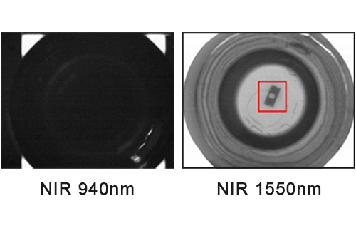
2) Infrared ranging method The principle of this method is similar to the triangulation method. The difference is that the system actively emits infrared rays as the ranging light source, and the rotation of the infrared light emitting diode replaces the rotation of the movable mirror.
3) Ultrasonic ranging method: This method measures distance based on the propagation time of ultrasonic waves between the camera and the subject. The optical instrument is equipped with an ultrasonic transmitter and receiver. During operation, the ultrasonic vibration generator emits ultrasonic waves with a duration of approximately 1/1,000 of a second, covering 10% of the entire image. After reaching the subject, the ultrasonic waves immediately return to the receiver for detection. An integrated circuit then calculates the focusing distance based on the round-trip time of the ultrasonic waves.
Infrared and ultrasonic autofocus use the active emission of light or sound waves for distance measurement, and are referred to as active autofocus.
2.2 Focus Detection Methods
Focus detection methods mainly include contrast method, split-image method, and phase method.
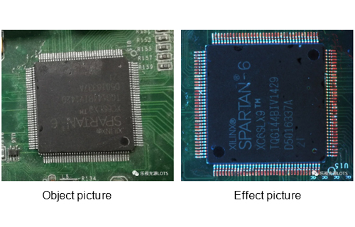
1) Contrast Method:
This method achieves automatic focus by detecting the image's edges. The sharper the image's edges, the greater its brightness gradient, or the greater the contrast between the subject and the background at the edges. Conversely, an out-of-focus image has blurred edges and a reduced brightness gradient, or contrast. The further out of focus, the lower the contrast. Using this principle, two photodetectors are placed equidistant from the film. The image of the subject is simultaneously formed on these two detectors through light splitting, and the contrast of the images is outputted separately. When the contrast outputs of the two detectors are equal, the image plane to be focused is exactly between the two detectors, coinciding with the film's position, and focusing is complete.
2) Split-image method:
A split-image wedge or microprism is placed at the focusing plate position (equal to the imaging plane). When the focus is exactly at the intersection of the split-image wedges or the vertex of the microprism, a single sharp image point is visible. When the focus deviates from this position, two separate images are seen through the split-image wedge, while numerous separate images are seen through the microprism, resulting in a blurred image. Focusing using a split-image wedge and microprism focusing plate is based on this principle. Because the focusing screen is perfectly conjugate to the imaging plane, accurate focus can be determined simply by visually observing the image on the focusing screen, which corresponds to the imaging plane. That is, if the split-image overlaps and the microprism image on the focusing screen is sharp, the image on the imaging plane is necessarily sharp; otherwise, the image is blurred. Focusing screens can be made in various configurations, such as ground glass surfaces, microconical surfaces, microprisms, split-image wedges, and annular lenses. This focus detection method is primarily used in single-lens reflex cameras.
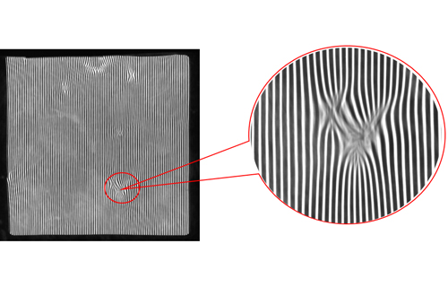
3) Phase Method:
This method achieves automatic focusing by detecting image offset. As shown in Figure 2, a grid composed of parallel lines is placed in the position of the photographic film, with the lines alternately transmissive and opaque. Two light-receiving elements are placed symmetrically about the optical axis behind the grid. The grid vibrates back and forth perpendicular to the optical axis. As shown in Figure 2, when the focal plane coincides with the grid, light passing through the transmissive lines of the grid reaches both light-receiving elements behind it simultaneously. However, when out of focus, the light beam reaches the two light-receiving elements sequentially, resulting in a phase difference between their output signals. These two signals with phase difference are processed by a circuit to control the actuator to adjust the position of the objective lens so that the focal plane coincides with the plane of the grid.
2.3 Principle of Lens-Separation Phase Detection
A lens-separation detection device consists of a set of splitter lenses and one or more distance-measuring components, or AF sensors, comprised of photosensitive elements. The following uses a CCD sensor-based distance-measuring component to illustrate the working principle of phase detection. The splitter lens splits the light passing through the camera lens into two beams, focusing them and projecting them onto the distance-measuring component. When the focus is accurately adjusted, the distance between the two beams generated by the splitter lens and projected onto the CCD array is constant. Consequently, the CCD remembers that the pair of CCD elements on the array, each charged by the beam, remains fixed. The distance between these two CCD elements is set during the design of the optical system and serves as the reference for focus detection.
When the focus is accurate, see Figure 3a. AB is used to represent the distance between a pair of CCD elements as a reference. When the focus is inaccurate, there are two possibilities: one is that the lens focus is in front of the subject, see Figure 3a. In this case, the distance between the two CCD elements receiving light is shorter than AB; the other is that the lens focus is behind the subject, see Figure 3c. In this case, the distance between the two CCD elements receiving light is longer than AB. Based on the distance between the pair of CCD elements receiving light, it can be determined whether the focus is accurate. The electrical signals generated by the two CCD elements are sent to the system's CPU central processing unit through the conversion circuit and the analog/digital conversion circuit. The CPU calculates the defocus amount [6], that is, the difference between the actual focus and the accurate focus, as well as the defocus direction, according to the set program and the difference between the distance between the pair of CCD elements and AB.
3. Image Processing-Based Autofocus
With the rapid development of computer hardware and digital imaging technology, real-time image processing has become possible. A computer captures a series of digital images through a lens and CCD, processes each frame in real time, determines whether focus is accurate and the image is clear, and provides feedback to control the lens's operation until the captured image meets the required specifications, completing autofocus.
Image processing-based autofocus has two major advantages: First, it provides more intelligent focusing, and the focus criteria are more flexible and diverse. Focus detection methods based on analog images only use the contrast between the object and the background (the gradient of the outline edge) as a criterion for image clarity. Digital image processing, however, not only utilizes gradient information but also extracts various other useful image information, such as frequency and phase. For images with high-frequency information, generally speaking, the more accurate the focus, the higher the frequency of the image signal, resulting in sharper edges; while out-of-focus conditions result in lower frequencies and relatively smoother edges. Furthermore, due to the flexibility of computer image processing, different focus criteria can be selected to meet different application requirements. For example, sometimes the desired target is only a certain part of the image, rather than the clarity of the entire image.
At this time, this part of the image should be processed and the judgment criteria should be extracted, and the contrast (edge gradient) of this part should be used as the basis for focusing.
Summary
Various autofocus methods have their own limitations. For example, the focusing methods of infrared ranging and ultrasonic ranging will cause the ranging system to malfunction or inaccurate focus when the target has a strong absorption effect on infrared light or ultrasonic waves. The contrast method is restricted by lighting conditions. When the ambient illumination is low, or the contrast of the subject is small, that is, the light and dark contrast of the scene is weak, the ranging accuracy is significantly reduced or even fails. For the optical system, when the aperture number is small, the light hole is large and the luminous flux is also large; as the aperture number increases, the light hole becomes smaller and the luminous flux also decreases. Since the allowable illumination range of the photoelectric element is limited, its focusing condition is limited by the aperture number. Taking the SLR camera as an example [11], in general, it is difficult to autofocus when the aperture number is greater than F8. The accuracy that the autofocus system can achieve varies according to the device parameters selected by the system and the manufacturing technology. When the allowable illumination range of the autofocus is EV-1~EV+3, the basically achievable accuracy is ±0.03~±0.1 mm. Image processing-based focus detection methods require significant computer resources, making them demanding for computer hardware. Furthermore, because this method uses the contrast between the object and the background (the gradient of the contour edge) as a criterion for image clarity, it is subject to lighting conditions, similar to the contrast method described previously. Digital image processing algorithms perform differently for different image types. Based on the results of various literature, the following methods have been generally accepted: squared gradient, TenenGrad (gradient), Laplace and Sobel variance, autocorrelation-based functions, Fourier transform, and wavelet transform.